Drive Medical Bobcat Assembly & Troubleshooting Guide
Nothing beats that new mobility scooter smell!
A variety of customers purchase a Drive Medical mobility scooter to help them travel independently from one place to another but need an assembly and troubleshooting guide when they encounter problems.
The Drive Medical Bobcat X is a lightweight transportable mobility scooter designed for comfort, performance, and value. Having purchased the product, this guide will help set up the lightweight disability scooter and can serve as a troubleshooting guide for any problem that may arise afterward.
How Do I Assemble the Bobcat X Disability Scooter?
The assembly for this Drive Medical mobility scooter is easy. Let’s start from the beginning:
- Once you have the Bobcat X box, carefully cut the packing straps off.

- The next step is to open up the box. You will want to remove the charger, the basket, the seat post and the seat from the package.
- To remove the Bobcat X from the box, we recommend having two people pick it up from the base of the package.
- After removing the Bobcat X base, grab the two armrests and take them out of the box.
- The Bobcat X will have protective wrapping that should be removed. Then, verify that all of the parts are present.
- Using best practices, the Bobcat X has been shipped with protective plastic sheets between the battery box and the battery box contacts that are on the base of the Bobcat X. Now, unlock the battery box.
- To remove the battery box, lift it straight up.
- Next, remove the protective plastic sheet. Return the battery box back into the Bobcat X base. Then, lock it in place.
- Slide the adjustable seat post into the seat post receiver on the base of the Bobcat X.
- Select a preferred height. Then, install the grenade pin through the base and the adjustable seat post.
- Install the seat post knob into the seat post receiver. It should then be tightened. Should the seat height be adjusted, loosen the seat post knob and remove the grenade pin. The adjustable seat post can be moved up or down as needed. Install the grenade pin and proceed to tighten the seat post knob.
- The next step is to remove the locking knob of the seat plate seat post receiver. Once that has been done, slide the seat unto the seat post.
- You will now want to install the locking knob back onto the seat plate.
- Using the tools, loosen the armrest-locking knob. Then, slide the armrest into the seat plate.
- Loosen the armrest-locking knob and slide the armrest into the seat plate.
- The armrest should be set at the most comfortable position. Once there, tighten it. Repeat the step for the other armrest.
- Set the armrest to the desired location and tighten the armrest-locking knob. Repeat on the other side.
- On the basket mounting brackets on the front of the tiller, slide the basket over it.
- Slide the basket over the basket mounting brackets on the front of the tiller.
- To adjust the angle of the tiller, loosen it with the tiller-locking knob. Once the desired angle is reached, tighten the tiller-locking knob.
- The Bobcat X has been shipped with the tiller locked in the straightforward position. To unlock the tiller, lift up on the tiller locking lever. When lifting up the base or the front section of the Bobcat X, the tiller should be locked.
- We’re almost there! Before using the scooter, we recommend charging the product. It is imperative that the Bobcat X scooter is turned off before charging.
- Plug the charger into any working 120-volt outlet. When it is correctly plugged into the outlet, a yellow light will illuminate.
- Next, plug the charger into the battery pack. The light on the charger will turn red and as the batteries charge the light will turn green when the batteries are fully charged. The battery pack can be charged either on or off the Bobcat X.
- To correctly operate the Bobcat X, the brake release must be in the drive position. This prevents the Bobcat X from being manually pushed.
- Turn the key to the on position.
- Set the speed control on the Bobcat X to a comfortable position.
- To go forward, you will want to push the forward side of the throttle lever towards the handlebar. However, to move in reverse, push the reverse side of the throttle lever towards the handlebar. To prevent an accident, the reverse speed is slower than the forward speed.
- The Bobcat X can be easily broken down into four pieces. First, remove the seat. Then, reach under the base to remove the grenade pin, the locks, along with the front and rear sections together. To prevent losing the grenade pin, it has been attached to the base.
- Finally, to verify the tiller is locked in place, see step 18. Lift up on the battery box while holding on to the front section of the base. This step will separate the front and rear sections.
- Next, unlock and remove the battery box. Reverse the above steps to reconnect the front and rear sections. The two yellow marks on the front section and the two yellow marks on the rear section must be aligned to reconnect both sections.
Flash Codes for the Bobcat X Disability Scooter
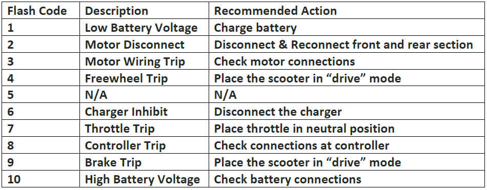
How do I troubleshoot the Bobcat X?
1 flash, pause, 1 flash(1,1)-Thermal fault. The controller has overheated. Allow it to cool down.
1,2- Indicates that the Forward-reverse throttle is either disconnected or out of tolerance.
To gain access to the components in the tiller assembly:
1. Remove the six screws underneath the tiller. Then, lift the panel off.
2. Unplug the throttle pot from the harness.
3. With your test meter set in the OHMS 20K function place the test leads on the outside terminals of the throttle potentiometer.
You should read 5K Ohms, + or –
4. Then, measure from one outside terminal to the middle terminal and note your findings.

5. Now measure from the other outside terminal to the middle.
Your two readings should be within 100 ohms of each other. If they are out of tolerance loosen the set screws on the assembly and adjust the electrical center point until they are within 100 ohms of each other. If this cannot be accomplished, replace the forward-reverse assembly, p/n
1,3- Indicates a fault in the speed pot circuit.
1. The next step is to remove the tiller cover. Refer to the procedure described in 1,2 to gain access.
2. Unplug the speed pot connector from the main harness.
3. With your multimeter set on the ‘200K Ohm position,’ measure the two outside terminals. You should read 100K ohms,+ or –
4. Put one test lead on the center terminal of the speed pot and the other on either end terminal. Rotate the knob from one end to the other. You should see the reading change from 0 to 100K, or, 100K to 0, — it all depends on which terminal you selected. If there are any non-linear or open spots on the control it should be replaced, p/n BC31001.
1,4 – Under-voltage fault- This indicates that the batteries either need to be charged or that they have deteriorated. To determine, test the battery voltage at the charger port. Set your multimeter to the 50 Volt DC function and insert the test probes into the charging port on the battery pack.
On a fully charged battery pack, you should be reading 26.5-27.5 volts. If it is less than 22 volts, then the batteries have to be replaced, p/n
1,5- Overvoltage fault. This happens when the charger doesn’t shut off when the batteries have reached their proper level. When this happens the batteries can be overcharged and ruined. The prudent action to take is to confirm the battery voltage using the procedure described in 1,4. If the voltage shown is greater than 29 volts then the charger must be replaced, p/n BC31055.
3,2- Indicates that the controller cannot “see” the electromagnetic brake
Make sure that the mobility scooter is not in the “Freewheel” mode. If it is, then push the red lever behind the right rear wheel to lock the brake.
1. If it is not, gain access to the controller by removing the black rear controller
2. On the controller, locate the white two-pin connector with the thin red and black wires. Unplug it. With your test meter in the 200 Ohm function, insert your test leads into the two terminals of the connector.
You should read approximately 45-60 ohms. If there is no reading at all or a short circuit, replace the brake, p/n BC310EB.
3,4- Throttle out of neutral at startup. If the throttle is not being displaced when the key is turned on it must be adjusted for “electrical center”. Follow the same procedure as outlined in 1,2.
Problems with no fault code displayed
1. If all the lights are lit but the chair does not drive, check that the charger is not plugged into the battery pack. If it is, the scooter goes into the
2. If all the lights are on, the scooter does not drive, but you can hear the electromagnetic brake “click” when you press the throttle, suspect that the motor is at fault.
A. Remove the black back shroud to expose.
B. Locate and unplug the large red and black wires which are between the large red and black battery wires and the brake connector.
C. With your meter set at the 200-ohm scale, you will then want to insert the test probes into the motor.
You should read between 2 and 6 ohms. If you get no reading or a direct short circuit, the motor is bad and must be replaced, p/n BC31125.
3. If you turn the key on and the scooter does not light or respond press the reset button on the rear shroud. If that does not fix the problem, locate the fuse by removing the control panel on the tiller.
Next, open the fuse holder and remove the fuse. Set your multimeter to the 200-ohm scale. Touch the red test probe to one blade of the fuse while touching the other blade with the black probe. If there is no continuity, however, the fuse is bad and must be replaced.
Additional Questions or Concerns
Should you have any additional questions regarding the directions laid out in this comprehensive document, we recommend reaching out to a skilled technician at our nationwide store.
We can be reached at (877) 721-7748.
Andrew Fatalo is the owner of Statewide Mobility Inc & Mobility Scooters Direct. He has been in the mobility product industry since 2005 and knows a ton about e-commerce marketing. He gives back to the handicap community by hosting mobility scooter and electric wheelchair give-aways which you can learn more about by following his companies on Facebook.